Fan Coil Unit Installation Guide
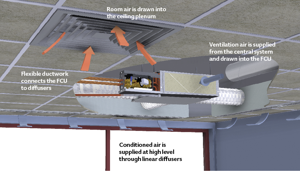
Module 101 The Evolution Of Fan Coils For Efficient Conditioning Of Room Air Cibse Journal
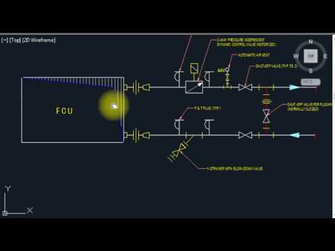
Hvac Fcu Fan Coil Units Valve Connection Installation Details Youtube
Method Of Statement For Installation Of Fan Coil Units And Packaged Air Conditioning Units Method Statement Hq
Https Www Titus Hvac Com File 11528 Tvb Iom 020816fnl Pdf
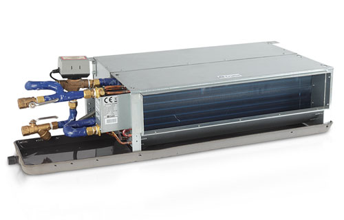
Horizontal High Performance Fan Coil Units Johnson Controls
Cassette Ceiling Fan Coil Unit Coowor Com
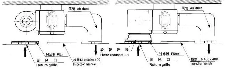
Drill the hole for the angle nut on the ceiling and fix the hanging rod.
Fan coil unit installation guide.
Https Surna Com Content Uploads 2017 07 Ceiling Mount Fan Coil Unit Manual Pdf

A Fan Coil Unit Fcu Is A Simple Device Consisting Of A Heating And Or Cooling Heat Exchanger Or Coil And Fan Fan Coil Unit Hvac Air Conditioning The Unit

How To Install Fan Coil Unit Fcu Vts Clima Step By Step In Professional Way By Mep Tech Tips Youtube

Vav System Air Conditioning System Hvac Design Refrigeration And Air Conditioning
Https Www Johnsoncontrols Com En Au Media Jci Be Australia Air Systems Fan Coil Units Files Be Productcatalog Ydfc Highstaticfancoilunits Pdf La En

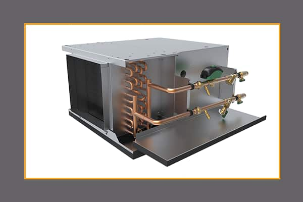
Fan Coil Unit Fcu Parts Google Search In 2020 Fan Coil Unit The Unit Coil

Condenser Coil Refrigeration And Air Conditioning Air Conditioner Compressor Repair Guide
How A Boiler Fan Coil Unit Air Handling Unit And Pump Work Together Hvac Heating System Youtube
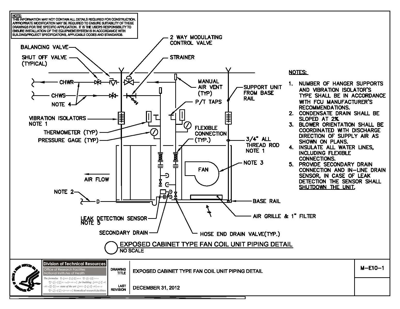
Nih Standard Cad Details

Monolink Fancoil Valve Connection Kit

Image Result For Hvac Duct Section

Fan Coil Unit Wikipedia

Fan Coil Units Extra Maintenance Steps Worth The Extra Effort Contracting Business

Trosten Industries A Fan Coil Unit Manufacturer Company Having Decades Of Experience In Manufacturing And Distribution Of Fan Coil Fan Coil Unit The Unit Coil

Air Conditioner Fan Coil Unit Chilled Water Model In 2020 Fan Coil Unit The Unit Split Ac

Pieces Of The Puzzle The Schematic Above Shows The Primary Components Of A Typical Air To Water Heat Pump Setup Ther Heat Pump System Heat Pump Water Heating

Part Of The Hvac System Fan Coil Units Are Used To Control The Temperature Of The Space In Which It Is Installed Finpower Fan Coil Unit The Unit Hvac System

Ceiling Concealed Fan Coil Units Draw Through Built In Unit With Horizontal Rear Inlet And Air Deliv Air Conditioning System Fan Coil Unit Digital Thermostat
3

Fan Coil Units Use Less Ductwork Than Ahu S Fan Coil Unit Duct Work Centrifugal Fan

Pin On Bs
Https Www Priceindustries Com Content Uploads Assets Literature Engineering Guides Fan Blower Coils Engineering Guide Pdf

Multi Zone Fan Coil Unit Controller Rickardair

See Figure Schematic Diagram Of Tested Chilled Ceiling Panel With Doas From Publication A Simulation Model To D Ceiling Panels Fan Coil Unit Water Systems
Source : pinterest.com
