Fin Fan Heat Exchanger Calculations
Shortcut Sizing For Air Cooled Heat Exchanger

Air Cooled Heat Exchangers Design Good Practices
New Page 1
Icljyihbucpywm
Improve Air Cooled Heat Exchanger Performance Aiche
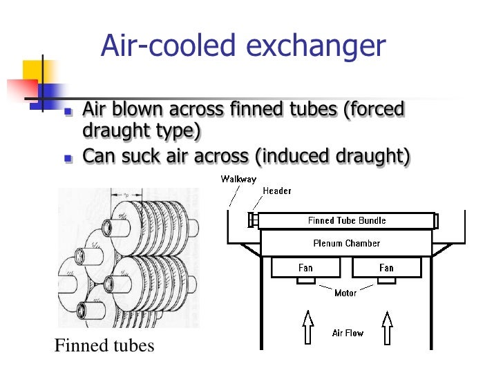
Air Cooled Heat Exchangers
It is also referred to as an air cooled heat exchanger.
Fin fan heat exchanger calculations.

Fin Fans How Many Can You Afford To Lose Movus
Air Cooler Air Cooler Design Calculation

Air Cooled Heat Exchangers An Overview Sciencedirect Topics
Pdf Acc Design Calculation Sudhir Bisen Academia Edu
Https Www Ndt Net Article Mendt2015 Papers Mendt2015 8 Pdf
Wet Surface Air Coolers Minimize Water Use By Maximizing Heat Transfer Efficiency

Lc Series Heat Exchanger Xchanger

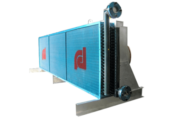
Plate Fin Core With Fan Air Cooled Heat Exchanger Multitherm Coils

Oil Gas Air Cooled Heat Exchange Header Plug Torque Calculation

Air Coolers

Fin Optimization In Heat Sinks And Heat Exchangers Advanced Thermal Solutions

Pdf Finned Tube Heat Exchanger With Circular Elliptical Rectangular Tubes With Water Vapor As Working Fluid

Pdf Air Side Pressure Drop In Plate Finned Tube Heat Exchangers
Heat Exchanger Finned Tube 8 Types You Should Know About

Finfoam Air Cooled Heat Exchanger Fin Fan Cleaning Youtube
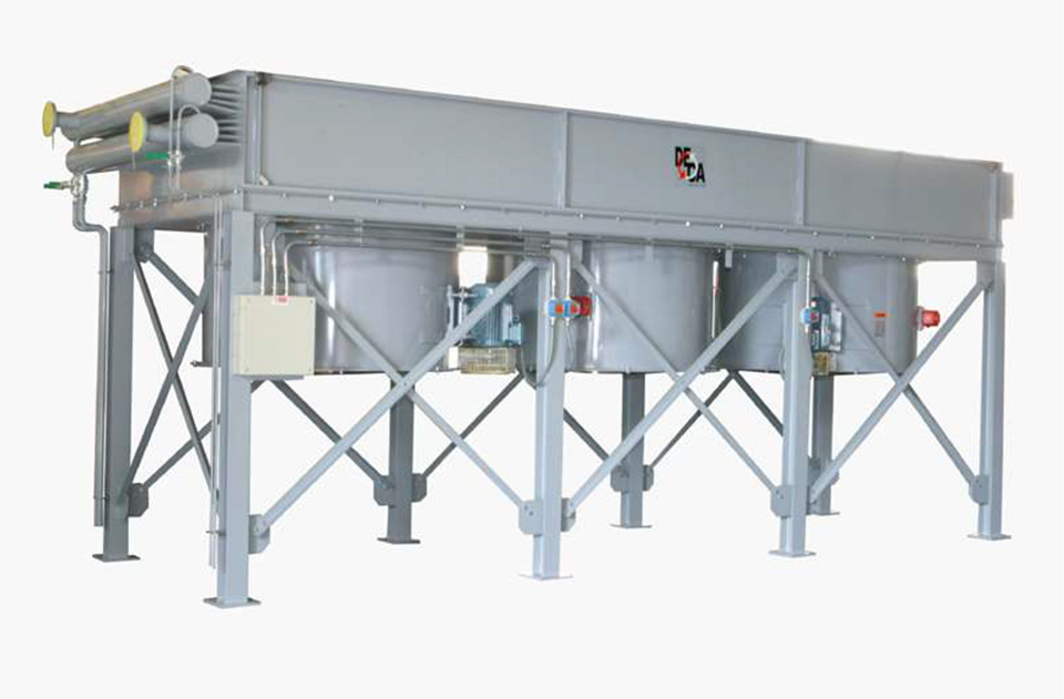
Fin Tube Fan Heat Exchanger Vosmik E C

Fin Fan Coolers Powerserv

Pdf Failure Analysis Of Alpha Mdea Air Cooled Heat Exchanger Of Co2 Removal Unit Based On The Semiquantitative Risk Based Inspection Method
Https Encrypted Tbn0 Gstatic Com Images Q Tbn 3aand9gcrjsyat5lkjlzarxcstlenk83ye8gpoqfwisepkc6kkxfzyqyci Usqp Cau
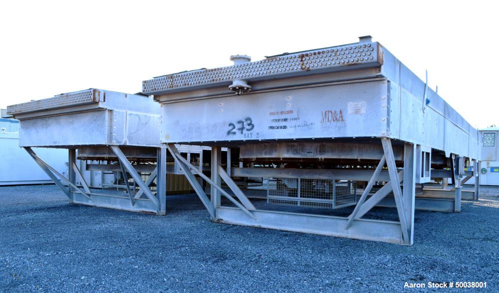
Unused Ecodyne Fin Fan Heat Exchanger System 14

Heat Exchangers Ipieca
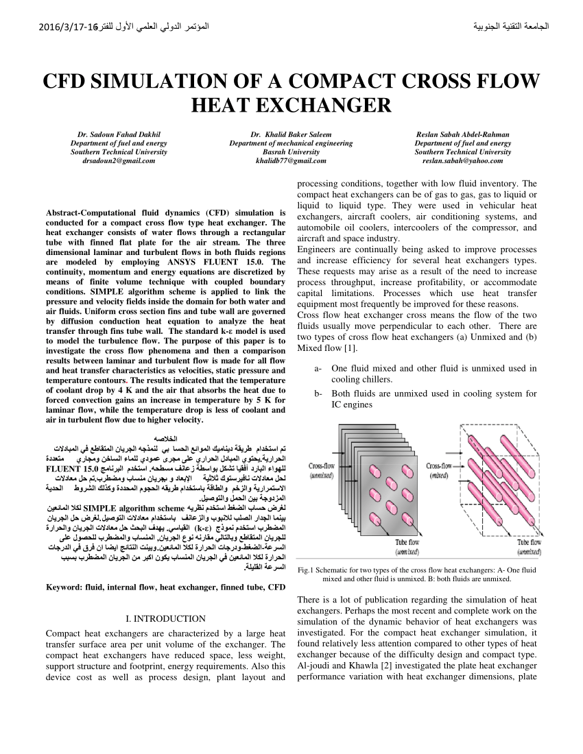
Pdf Cfd Simulation Of A Compact Cross Flow Heat Exchanger
Pdf Optimization Of Air Cooled Heat Exchanger Design Using Htri Research And Scientific Innovation Society Rsis International Academia Edu

Cold Jet Dry Ice Cleaning Fin Fan Coolers Improve Efficiency 2019 Youtube
Source : pinterest.com
